A practical guide using the PCB terminal markings if you are providing your own cable, Spur cables purchased with box are prewired for plug in and play simplicity.
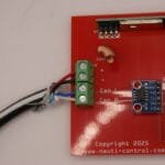
The reference photo below shows the actual terminal block on the Nauti-Control PCB as supplied.
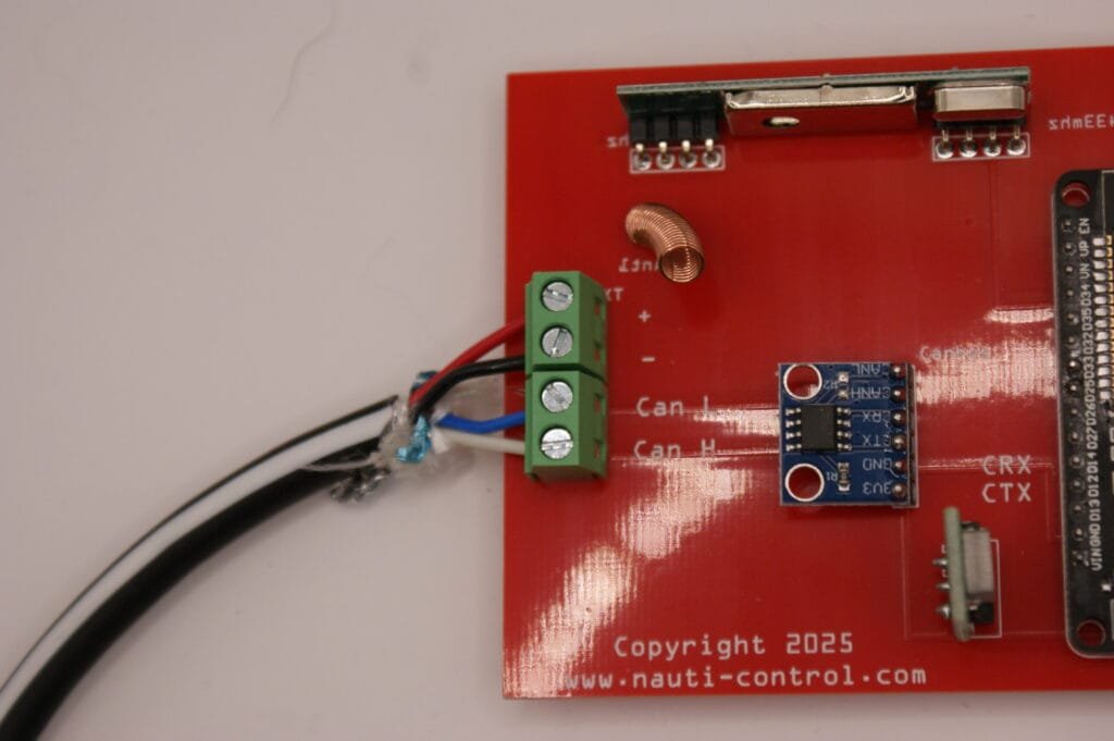
Identifying the terminals on the PCB
Looking at the screw terminal block on the board (as shown in the photo), the PCB is labelled:
From top to bottom:
- + → Network power positive (+12 V)
- – → Network power negative (0 V / ground)
- CAN L → CAN Low
- CAN H → CAN High
SeaTalk NG and NMEA 2000 wiring
For SeaTalk NG and standard NMEA 2000 spur or backbone cables, connect as follows:
| Network cable colour | Connect to PCB terminal |
|---|---|
| Red | + |
| Black | – |
| Blue | CAN L |
| White | CAN H |
This is a direct, one-to-one connection.
SimNet wiring (colour difference)
SimNet uses different colours for the CAN data pair. The electrical signals are identical, but the colours must be mapped correctly.
| SimNet cable colour | Signal | PCB terminal |
|---|---|---|
| Red | +12 V | + |
| Black | 0 V / Ground | – |
| Green | CAN Low | CAN L |
| Yellow | CAN High | CAN H |
⚠️ Important:
Do not connect SimNet colours directly without checking. Reversing CAN H and CAN L will prevent the device from communicating on the network.
Power and termination notes
- The Nauti-Control N2K Box is powered from the network
- Do not add a second power feed if the backbone is already powered
- The backbone must be terminated with 120 Ω resistors at both ends
- The Nauti-Control should connect via a spur, not inline with the backbone
Final wiring check (recommended)
Before applying power:
- Confirm each wire matches the PCB label
- Check CAN H and CAN L are not swapped
- Verify correct polarity on + and –
- Ensure the backbone is properly terminated
Once powered, the Nauti-Control N2K Box will join the network automatically and begin transmitting and receiving NMEA 2000 data.

Leave a Reply
You must be logged in to post a comment.